Current Electricity
Electric current is defined as the rate of flow of charge along a conductor.
Mathematically,
\[ I = \frac{Q}{t} \]
where:
- I = Electric current (Amperes, A)
- Q = Quantity of charge (Coulombs, C)
- t = Time (seconds, s)
The unit of electric current is the ampere (A).
Ohm’s Law
Ohm’s Law states that the current flowing through a metallic conductor is directly proportional to the potential difference across its ends, provided the temperature and other physical conditions remain constant.
Mathematically,
\[ V \propto I \]
\[ V = IR \]
or rearranging,
\[ I = \frac{V}{R} \quad \text{or} \quad R = \frac{V}{I} \]
where:
- V = Potential difference (Volts, V)
- I = Current (Amperes, A)
- R = Resistance (Ohms, Ω)
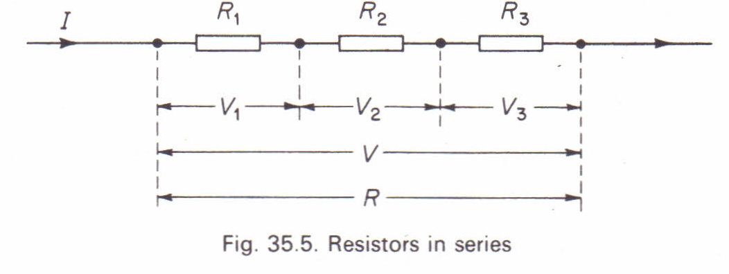
Resistors in Series
When resistors are connected in series, the total or equivalent resistance is given by:
\[ R = R_1 + R_2 + R_3 \]
 Credit: PhysicsMax
Key properties of resistors in series:
- The same current flows through each resistor.
- The potential difference across each resistor depends on its resistance.
- The total potential difference across the entire series connection is equal to the sum of the individual potential differences.
Resistors in Parallel
When resistors are arranged side by side such that their corresponding ends join together at two common junctions, the arrangement is known as a parallel connection.
The total or equivalent resistance \( R \) is given by:
\[ \frac{1}{R} = \frac{1}{R_1} + \frac{1}{R_2} + \frac{1}{R_3} \]
For parallel circuits:
- Each resistor has a different current, but the same voltage is applied across all resistors.
- The total current in the circuit is given by: \[ I = I_1 + I_2 + I_3 \]
- Using Ohm’s Law \( V = IR \), we can express the total current as: \[ \frac{V}{R} = \frac{V}{R_1} + \frac{V}{R_2} + \frac{V}{R_3} \]
Thus, the equivalent resistance of the combination is:
\[ \frac{1}{R} = \frac{1}{R_1} + \frac{1}{R_2} + \frac{1}{R_3} \]
Factors Affecting Electrical Resistance
Electrical resistance is influenced by the following factors:
- Length of conductor: Resistance increases with length.
- Cross-sectional area of conductor: Resistance decreases as the cross-sectional area increases.
- Temperature: Resistance generally increases with temperature for metallic conductors.
- Type or substance of material: Different materials have different resistivities.
Resistivity and Electrical Conductivity
Resistivity
Resistivity is the resistance of a unit length of material with a unit cross-sectional area. It determines how strongly a material opposes the flow of electric current. When:
- \( R \) is measured in ohms (\(\Omega\))
- \( A \) is measured in square meters (\(m^2\))
- \( L \) is measured in meters (\(m\))
The unit of resistivity (\(\rho\)) is ohm-meter (\(\Omega m\)). The higher the resistivity of a material, the poorer it is as an electrical conductor. This is why conductivity is used to describe a material’s ability to carry current. A material with high conductivity allows current to flow more easily, while a material with high resistivity hinders current flow.
Resistance (\( R \)) is given by:
\[ R \propto \frac{L}{A} \] \[ R = \frac{\rho L}{A} \]where:
- \( R \) = Resistance (\(\Omega\))
- \( L \) = Length of the wire (\(m\))
- \( A \) = Cross-sectional area of the wire (\(m^2\))
- \( \rho \) = Resistivity (\(\Omega m\))
Electrical Conductivity
Electrical conductivity (\( \sigma \)) measures how easily a material allows electric current to pass through when a potential difference is applied at a given temperature. It is the reciprocal of resistivity (\(\rho\)) and is given by:
\[ \sigma = \frac{1}{\rho} \]where:
- \( \sigma \) = Electrical conductivity (\( \text{S/m} \))
- \( \rho \) = Resistivity (\(\Omega m\))
Internal Resistance of a Cell
In the absence of an external conductor, a chemical cell develops a potential difference \( E \), which is called the electromotive force (emf). When the cell's terminals are connected and current flows, the electrolyte inside the cell offers resistance. This is known as the internal resistance (\( r \)).
The potential difference required to drive a current through the internal resistance of the cell is \( Ir \) (lost p.d.), while that required to drive a current through an external conductor is \( IR \) (terminal p.d.).
\[ I = \frac{E}{R + r} \]The emf of the cell can be expressed as:
\[ E = I (R + r) = IR + Ir = V + v \]where:
- \( E \) = Electromotive force (emf)
- \( V \) = Terminal p.d.
- \( r \) = Internal resistance of the cell
- \( R \) = External resistance
- \( v \) = Lost p.d.
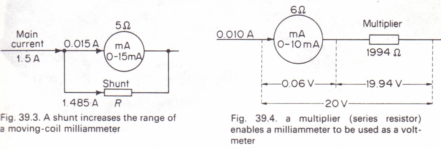
Galvanometer Conversion
Conversion of Galvanometer to Ammeter (Shunt)
An ammeter is used to measure currents, whereas a galvanometer detects and measures very small currents. A galvanometer can be converted into an ammeter by connecting a suitable resistor in parallel with it. This parallel resistor is called a shunt.
The shunt is a low-resistance wire that diverts most of the current, allowing only a small fraction to pass through the galvanometer.
 Credit: PhysicsMax
Conversion of Galvanometer to Voltmeter
A galvanometer, which measures very small currents, can be converted into a voltmeter by connecting a high-resistance component (also called a multiplier) in series with it. This setup allows the device to measure voltage instead of current.
Work Done in an Electric Circuit / Electrical Energy
The work done when electricity flows from one point to another at a different potential is given by:
\[ W = QV \]
The unit of work done is the Joule (J), which is defined as:
\[ 1 \text{ Joule} = 1 \text{ Coulomb} \times 1 \text{ Volt} \]
Since charge (\(Q\)) is given by:
\[ Q = It \]
We can substitute this into the equation:
\[ W = IVt \]
Using Ohm’s Law (\( V = IR \)), we derive other forms of the work equation:
\[ W = I^2 R t \]
\[ W = \frac{V^2}{R} t \]
Electrical Power
Power (\( P \)) is defined as the rate at which work is done:
\[ P = \frac{\text{Work done (Joules)}}{\text{Time taken (Seconds)}} \]
Since work done is given by \( W = IVt \), dividing by \( t \) gives:
\[ P = IV \]
Using Ohm’s Law, alternative forms of power equations are:
\[ P = I^2 R \]
\[ P = \frac{V^2}{R} \]
Units of Power:
- The unit of power is the Watt (W).
- Larger units of power include:
- 1 kilowatt (kW) = 1000 watts
- 1 megawatt (MW) = \( 10^6 \) watts = \( 10^3 \) kW
Measurement of Resistance
Resistance (\(R\)) can be determined using the following methods:
- Voltmeter – Ammeter method
- Wheatstone bridge
- Meter bridge
Voltmeter – Ammeter Method
Using this method, an ammeter and a voltmeter are connected in a circuit, and their values are recorded. By varying the variable resistor, a graph of voltage (\(V\)) against current (\(I\)) can be plotted. The slope of this graph represents the resistance (\(R\)), given by Ohm’s law:
\[ R = \frac{V}{I} \]Wheatstone Bridge
The Wheatstone bridge is an instrument used for accurately measuring resistance. It consists of four resistors \( R_1, R_2, R_3, R_4 \) connected to form a closed circuit. When the resistances are adjusted, a stage is reached where no current flows through the galvanometer at the center, indicating balance.
The condition for balance in a Wheatstone bridge is:
\[ I_1 R_1 = I_2 R_3 \] \[ I_1 R_2 = I_2 R_4 \]Dividing both equations:
\[ \frac{R_1}{R_3} = \frac{R_2}{R_x} \] Credit: Wikipedia
Meter Bridge
A meter bridge is used to measure unknown resistance using the principle of a Wheatstone bridge. The relation is:
\[ \frac{R}{S} = \frac{L_1}{L_2} \]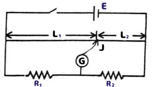 Credit: CramA1